Cavities and voids
Volumes without material or with a filling different from the surrounding concrete.
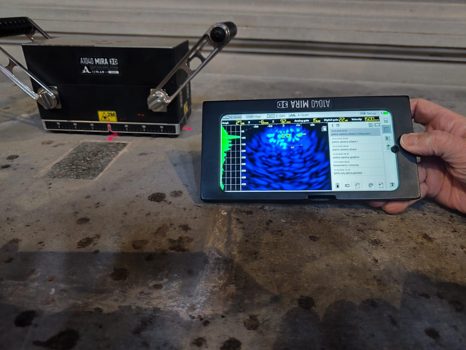
Seeing inside a structure through the response of ultrasonic waves.
Ultrasonic tomography analyses the internal structure of concrete through the reflection of elastic wave pulses, producing B-scan sections and, through grid acquisitions, three-dimensional representations.
Ultrasonic tomography is a non-destructive testing method based on the pulse-echo principle: short elastic wave pulses are applied to the structural element and the response reflected by the material is analysed.
Reflection occurs where the wave path encounters a change in the properties of the medium. Response intensity depends on acoustic impedance contrast: the greater the difference between the concrete and the encountered element, the more pronounced the recorded reflection.
Pulse emission
Short elastic wave pulses are generated and propagate within the concrete element.
Reflection
The pulse is reflected at surfaces that interrupt material continuity.
Acoustic impedance contrast
The magnitude of the reflection depends on the acoustic impedance contrast between the concrete and the element or discontinuity encountered.
Signal acquisition
The reflected signal is acquired and recorded with its corresponding travel times and amplitudes.
Response processing
The acquired data are processed to produce a representation of the investigated volume's response.
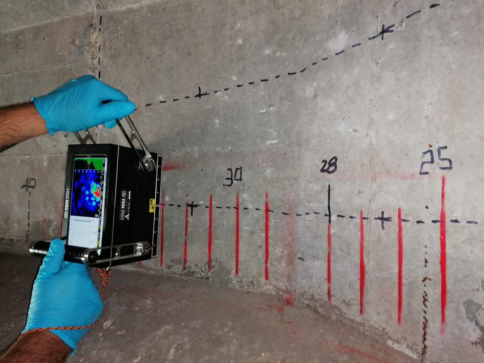
The information pathway, from the emitted pulse to the three-dimensional representation, follows a sequence defined during survey design.
Ultrasonic pulse
Emission of elastic waves into the material.
Reflection
Response at acoustic contrasts.
Acquisition
Recording of the reflected signal.
B-scan
Section of the investigated volume.
Grid acquisition
Repetition on a defined grid.
3D reconstruction
Three-dimensional combination of the data.
In the system documented in Novatest campaigns, an array of 12 sensors operates alternately as transmitter and receiver, generating many path combinations at each position. This characteristic relates to the specific system used and must not be regarded as a property shared by all tomographic systems.
The information obtainable depends on the acoustic contrast between the elements present and the concrete, as well as acquisition conditions. Detectability of an anomaly therefore cannot be assumed in advance.
Volumes without material or with a filling different from the surrounding concrete.
Separation surfaces that may generate a detectable reflection.
Internal variations in material configuration or compactness.
Separations between layers or between materials with different properties.
Reinforcement, inserts and other embedded elements with high acoustic contrast.
Deviations from the expected or documented geometry of the element.
A single acquisition produces a section of the investigated volume, called a B-scan. Repeating acquisitions on a defined grid allows the data to be combined into a three-dimensional representation of the analysed portion of the element.
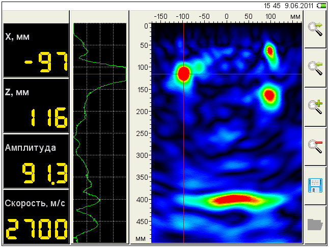
Single acquisition
B-scan section: recorded reflections are displayed as a function of position and depth, showing the response of the investigated volume.
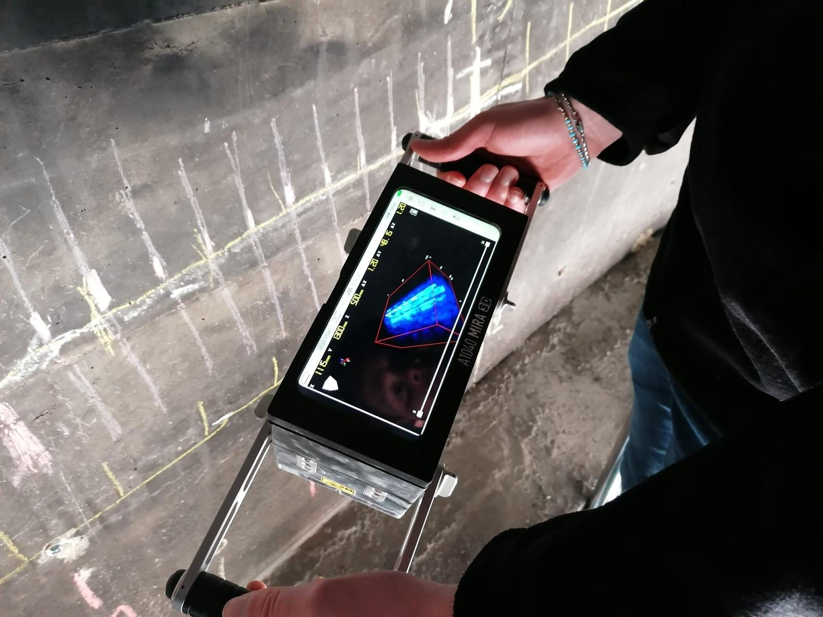
Grid acquisition
Three-dimensional reconstruction obtained by combining successive grid acquisitions, displaying the internal configuration of the analysed portion.
In specific documented campaigns, ground-penetrating radar was used first to reconstruct the element's internal geometry, locate reinforcement and embedded elements, and guide subsequent tomographic acquisition towards relevant areas.
The two methods provide different types of information: their combination is a documented example of an investigation strategy, not a mandatory procedure or a sequence applicable in every context.
GPR
Location and geometry
Ultrasonic tomography
Further investigation of internal characteristics
Data correlation
Integrated interpretation of the acquired information
In elements containing prestressing cables or strands, ultrasonic tomography can contribute to analysing the internal configuration, provided that the investigation is designed with the element's characteristics in mind.
Preliminary assessment of the element's geometry and thickness, verification of available concrete cover and choice of viewing direction decisively influence the quality of the information obtainable.
Technical note
Ultrasonic tomography is a diagnostic tool: result quality depends on appropriate survey design and data interpretation.
In 2019 Novatest carried out a diagnostic campaign on the Via Mario de Bernardi viaduct near Fiumicino Airport, aiming to obtain information on the internal configuration of the existing structural elements.
The campaign used ultrasonic tomography, GPR and digital radiography. This page focuses on tomography's contribution and its methodological relationship with ground-penetrating radar investigations.
GPR provided preliminary information on the internal configuration, while tomography enabled a more detailed examination of the element's response through ultrasonic acquisitions.
Explore the full bridge and viaduct investigation case:
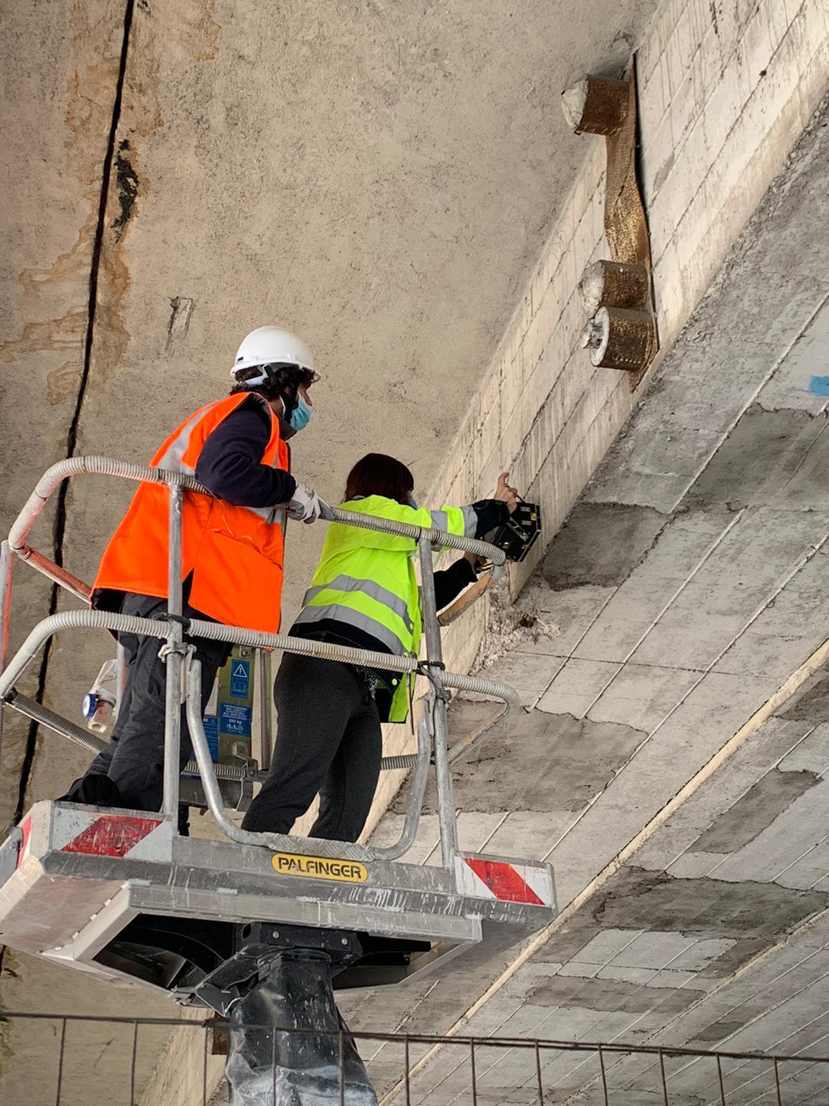
The campaigns described used the A1040 MIRA tomographic system. Equipment nevertheless remains a supporting element: result quality depends on survey design and technical interpretation of the acquired data.
Ultrasonic tomography can be considered when it is necessary to:
The method must be selected according to the diagnostic objective, the structure and operating conditions.
The choice of method depends on the investigation objective, the element's geometry and operating conditions.