Reinforcement
Can help locate the bars and qualitatively reconstruct their arrangement.
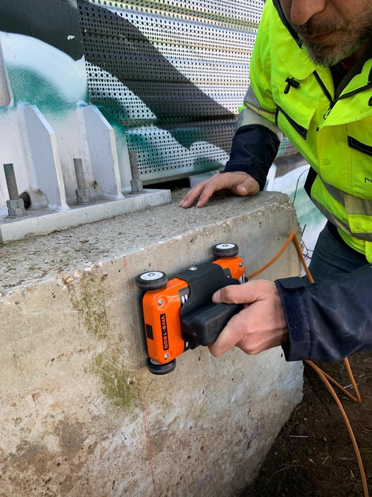
Investigating the inside of structural elements without demolition.
Ground Penetrating Radar applied to structural diagnostics uses high-frequency electromagnetic pulses to identify elements, discontinuities and variations in material properties inside concrete structures.
GPR is an indirect, non-invasive method. An antenna sends short electromagnetic pulses into the concrete; their propagation depends on the electrical properties of the material crossed.
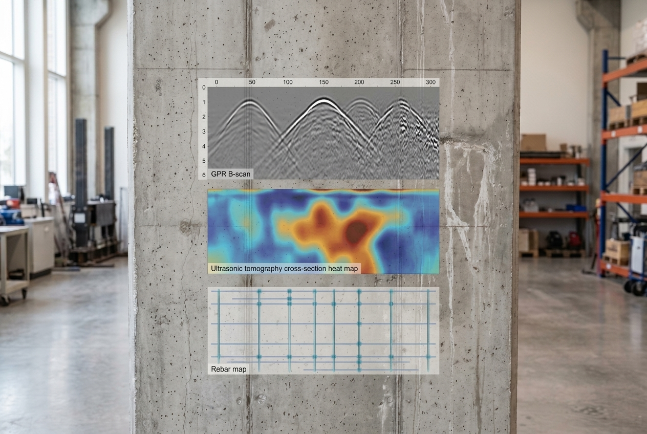
When the signal encounters an interface between materials with different electromagnetic properties, part of the energy is reflected and received by the antenna. The response recorded along the profile is processed and represented as a radargram, whose interpretation requires comparison with known geometry, materials and conditions of the element.
Emission and reception on the surface of the element.
High-frequency signal sent into the material.
Path conditioned by electromagnetic properties.
Variation encountered in the investigated volume.
Part of the energy returns to the surface.
Representation of signals along the acquired profile.
Technical reading correlated with known geometry and conditions.
The evidence depends on electromagnetic contrast, the frequency used and acquisition conditions. The radargram provides indications to be interpreted: it does not automatically diagnose corrosion, moisture or deterioration.
Can help locate the bars and qualitatively reconstruct their arrangement.
Can reveal inserts, ducts or other elements with strong electromagnetic contrast.
The response may indicate volumes with properties different from the surrounding concrete.
Local signal variations may suggest areas to investigate further with targeted checks.
Can help distinguish interfaces, thicknesses and changes in internal configuration.
The radargram may show variations to be interpreted together with other data, without automatic diagnosis.
Metal bars produce recognisable reflections which, when acquisition geometry and signal quality are adequate, can help locate their position and qualitatively reconstruct their arrangement within the structural element.
Reading coordinated profiles allows the evidence to be organised spatially and supports the choice of areas in which to carry out subsequent checks, local tests or further investigation with other methods.
| Aspect | Structural GPR | Covermeter |
|---|---|---|
| Principle | Electromagnetic waves | Local magnetic or electromagnetic principle |
| Acquisition | Coordinated profiles and grids | Point measurements or local scans |
| Reporting | Radargrams and mappings | Position of reinforcement and measurement/estimate of concrete cover |
| Reading | Interpretation of internal configuration | Local verification of metallic elements |
GPR and the covermeter can be used in a complementary way when the objective of the survey requires it.
A traceable mapping requires a reference system with origin and longitudinal and transverse axes. Grid spacing and scan directions are chosen based on the expected size of the elements and the level of detail required.
Reference, origin, axes and spacing defined.
Longitudinal and transverse profiles.
Recording of the response along each profile.
Corrections and treatment consistent with the survey.
Spatial correlation of evidence.
Measurement conditions
Materials with high conductivity can rapidly attenuate the signal and reduce the depth that can be investigated. Rapid attenuation may be associated with different conditions and does not, by itself, constitute a diagnosis of moisture, corrosion or deterioration.
The survey configuration is not standard: frequency, grid, directions and processing procedures must be defined starting from the diagnostic question and the element to be investigated.
Clarifying which information must support the technical decision.
Balancing resolution, depth and characteristics of the element.
Establishing origin, axes and coordinate system of the survey.
Defining spacing and directions based on the scale of the targets.
Collecting traceable profiles consistent with the survey plan.
Applying appropriate procedures without separating the data from its context.
Reading reflections and anomalies considering geometry and material.
Delivering results, limitations and indications useful for subsequent decisions.
In specific campaigns GPR can provide preliminary information on internal geometry and the position of elements, helping to select the areas in which to further investigate the concrete's response using ultrasonic tomography.
This is an example of documented integration, not a mandatory procedure: methods and sequence must be chosen based on the diagnostic question.
Discover ultrasonic tomographyGPR
Location and geometry
Ultrasonic tomography
In-depth investigation
Data correlation
Integrated reading of information
In 2019 Novatest conducted a diagnostic campaign on the Via Mario de Bernardi Viaduct, at Fiumicino Airport. GPR was used to qualitatively define the arrangement of the rebars in the central beam and organise subsequent investigations.
116 radar sections were acquired on the central beam. The radargrams were subsequently organised by sector, maintaining correspondence with the reference system adopted on site.
The contribution of GPR was the qualitative reading of the internal configuration: the data guided the diagnostic programme without replacing correlation with ultrasonic tomography and digital radiography.
Discover the full case study on bridge and viaduct surveys:
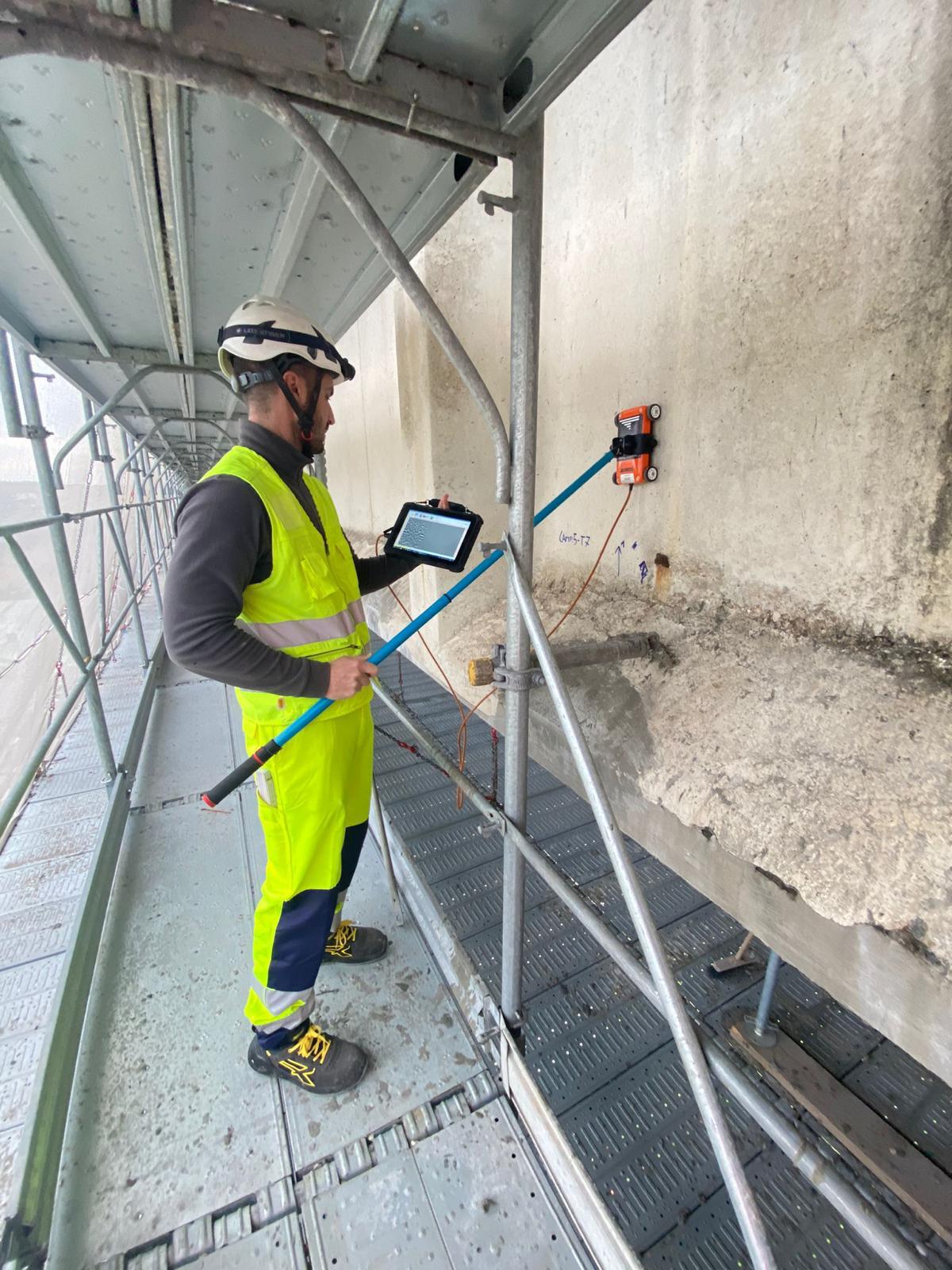
GPR is a diagnostic tool whose effectiveness depends on the correct choice of frequency, acquisition geometry and the characteristics of the investigated element.
Concrete diagnostics requires high-frequency systems and configurations consistent with the required resolution, depth and accessibility. Instrumentation remains subordinate to survey design, acquisition quality and technical interpretation.
Discover Novatest GPR solutionsThe choice of GPR system and acquisition mode depends on the element to be investigated, the information required and the operating conditions.